VGA Monitor Output from an Arduino
One of the coolest
things about programming on a platform for the first time is making something
graphical or somehow otherwise tangible to the eye. Terminal apps generally aren't very exciting
because they're just text, but making an application with its own window &
graphics is much more exciting for the beginner. If it's a microcontroller, making that LED
blink is a first big step toward future fun.
However, there is a lot more to do when it comes to making graphical
output from microcontrollers -- output on 7-segment displays, an LED matrix,
LCD touchscreens, or the pinnacle & mainstay of computer displays -- the
monitor.
Having taken a class
in FPGA design and becoming fascinated with video output without needing an
operating system, I decided to look into what it'd take to use the Arduino to
produce VGA output. It turns out the hardware
requirements can be somewhat hard to come by these days:
- A nice, old, tolerant CRT monitor -- my LCD monitors won't support this
- A breadboard
- Several resistors of various values; pick your own after reading below
Once you have the
prerequisite hardware, you need to acquire some esoteric knowledge about the
way Atmels and many other microcontrollers work. This definitely isn't beginner-level stuff;
it took a little while to pore over the Atmega328 datasheet to figure out just
what settings are required to make the analog* signals required to drive a VGA
monitor. Instead of making you repeat
all this research, I'll just give it to you.
I've attempted to make explanations in the comments, but if anything is
unclear, please refer to the datasheet.
The schematic
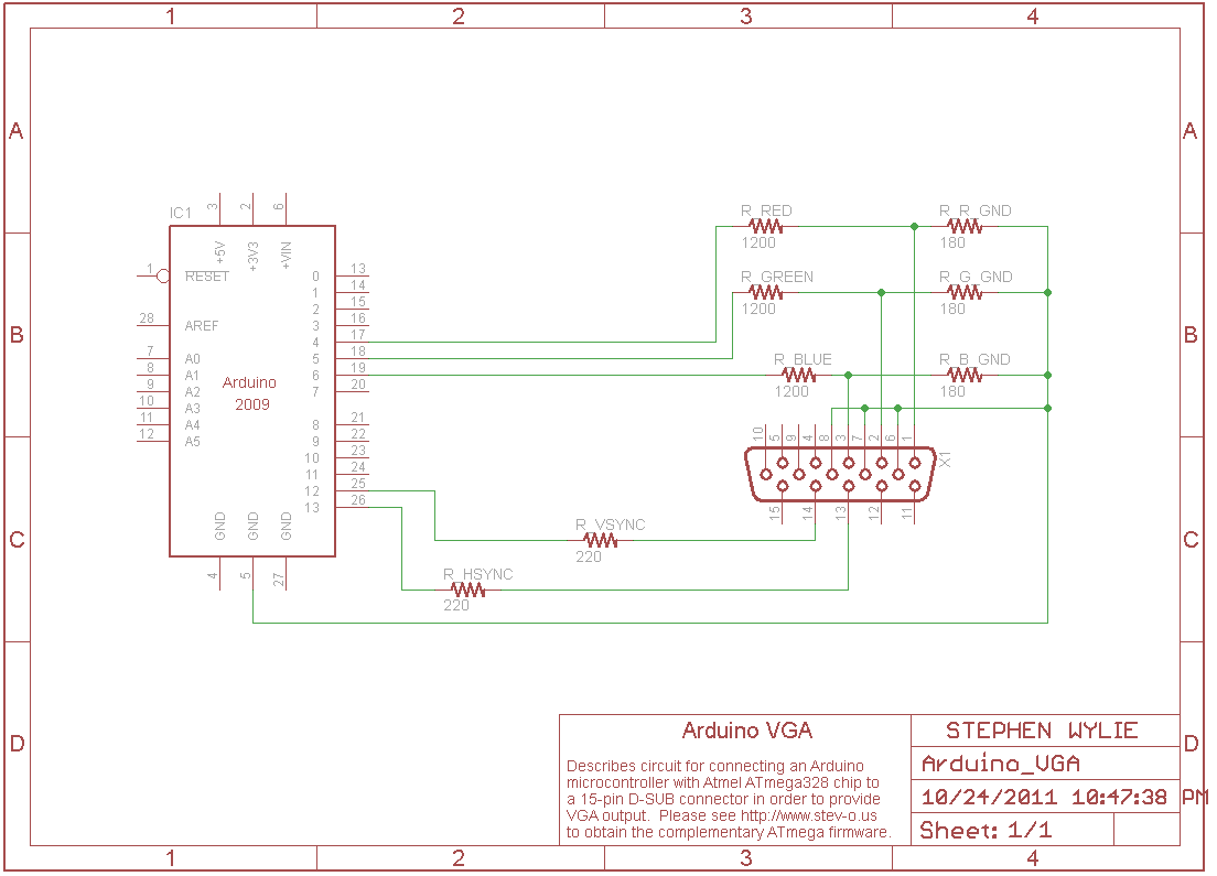
Note the voltage dividers put in place to change the output of the
Arduino from 5 volts down to the maximum 0.7 volts allowed by VGA hardware. Arduino pins 13 & 12 (sync) go out to one
220-ohm resistor each, and 7, 4, & 2 (the RGB pins) each go to their own
voltage divider with R1 = 1200 ohms and R2 = 180 ohms. Some further notes:
- Pin 9 on the D-SUB connector should really be wired to ground. However, my circuit managed to work without doing this, so it's not in the schematic.
- I can't remember the rhyme or reason for putting a resistance on the sync lines of specifically 220 ohms.
- The 1200 ohm and 180 ohm resistors are in place as a voltage divider, since the maximum voltage the RGB pins in a VGA monitor can take is 0.7V. These resistor choices lead to (180 / (1200 + 180)) * 5V ~= 0.65V. You can use any other combination as long as it leads to the correct voltage.
Arduino firmware
The firmware is
designed to consolidate the Red, Green, and Blue values for each
"pixel" into 3 consecutive bits.
While this prevents any interesting variations in color (i.e. only eight
colors are possible), and isn't truly "analog", it helps speed up
processing time because you can cram 2 "pixels" into the same
byte. The next pixel can be shown simply
by shifting the register left by 4 bits, which takes fewer clock cycles than
loading the value from the flash ROM.
(This kind of causes some pixels to be slightly narrower than
others.) Speaking of pixels and
resolution, this code generates an image with a resolution of approximately
376x282 @ 60 Hz. Here are a few places I
got guidance from on my quest to write this firmware:
- http://arcanebolt.net/ - My code is based off theirs, but heavily modified.
- http://www.cs.unc.edu/Research/stc/FAQs/Video/GTF_V1R1.xls - A GTF spreadsheet you can use for finding out what frequency and timings to use given the desired VGA resolution and refresh rate you specify. If this spreadsheet doesn't work out for you, the one I used originally has been recovered and I can share it. I don't know where it came from originally.
- Lots of Google searches for "vga pinout" and "vga timing specification", etc.
#include
<avr/interrupt.h>
#include
<avr/pgmspace.h> // for PROGMEM
//
horizontal line counter (negative is during vertical blanking)
int
hzCount = -10;
int
vCount = 0;
int
timingCount = -10;
int
base = 0;
unsigned
short int OCR1AMEM = 0;
unsigned
int pixRow = 0;
prog_uchar*
curPix = 0;
unsigned
int displayInt;
int
k; // counter variable
char
myChar;
//
==============
//
Pinout:
#define
HSYNC 0b00100000; // 13: HSYNC (Port B5)
#define
VSYNC 0b00010000; // 12: VSYNC (Port B4)
#define
BLACK 0b00000000; //
Black 0x00
#define
BLUE 0b01000100; //
6: Blue (Port D6) 0x40, 0x04, 0x44
#define
GREEN 0b00100010; // 5: Green
(Port D5) 0x20, 0x02, 0x22
#define
RED 0b00010001; //
4: Red (Port D4) 0x10, 0x01
#define
CYAN 0b01000100; //
Cyan 0x60
#define
YELLOW 0b00110011; //
Yellow 0x30
#define
MAGENTA 0b01010101; //
Magenta 0x50
#define
WHITE 0b01110111; //
White 0x70
//
prog_uchar
//
prog_uint32_t signMessage[] PROGMEM = {0x04108000, 0x00000410,
0x00808000, 0x00000080}; // , 0x92009292, 0x92000092, 0x00009292, 0x00920029};
prog_uchar
signMessage[] PROGMEM = {/*this is where a whole lot of hex numbers
go for your custom image*/};
//===
//
Others go to GND
//
=======
//
hurry up & wait
#define
NOM asm("nop");
#define
NOM5 asm("nop\nnop\nnop\nnop\nnop");
#define
NOM10 asm("nop\nnop\nnop\nnop\nnop\nnop\nnop\nnop\nnop\nnop");
#define
NOM20 asm("nop\nnop\nnop\nnop\nnop\nnop\nnop\nnop\nnop\nnop\nnop\nnop\nnop\nnop\nnop\nnop\nnop\nnop\nnop\nnop");
void
hLine(void)
{
curPix
= signMessage + base;
PORTD
= pgm_read_byte_near(curPix);
curPix++;
PORTD = PORTD << 4;
PORTD
= pgm_read_byte_near(curPix);
curPix++;
PORTD = PORTD << 4;
PORTD
= pgm_read_byte_near(curPix);
curPix++;
PORTD = PORTD << 4;
PORTD
= pgm_read_byte_near(curPix);
curPix++;PORTD
= PORTD << 4;
PORTD
= pgm_read_byte_near(curPix);
curPix++;PORTD
= PORTD << 4;
PORTD
= pgm_read_byte_near(curPix);
curPix++;
PORTD = PORTD << 4;
PORTD
= pgm_read_byte_near(curPix);
curPix++;
PORTD = PORTD << 4;
PORTD
= pgm_read_byte_near(curPix);
curPix++;
PORTD = PORTD << 4;
PORTD
= pgm_read_byte_near(curPix);
curPix++;
PORTD = PORTD << 4;
PORTD
= pgm_read_byte_near(curPix);
curPix++;
PORTD = PORTD << 4;
//
pix 21-
PORTD
= pgm_read_byte_near(curPix);
curPix++;
PORTD = PORTD << 4;
PORTD
= pgm_read_byte_near(curPix);
curPix++;
PORTD = PORTD << 4;
PORTD
= pgm_read_byte_near(curPix);
curPix++;
PORTD = PORTD << 4;
PORTD
= pgm_read_byte_near(curPix);
curPix++;
PORTD = PORTD << 4;
PORTD
= pgm_read_byte_near(curPix);
curPix++;
PORTD = PORTD << 4;
PORTD
= pgm_read_byte_near(curPix);
curPix++;
PORTD = PORTD << 4;
PORTD
= pgm_read_byte_near(curPix);
curPix++;
PORTD = PORTD << 4;
PORTD
= pgm_read_byte_near(curPix);
curPix++;
PORTD = PORTD << 4;
PORTD
= pgm_read_byte_near(curPix);
curPix++;
PORTD = PORTD << 4;
//
pix 40-
NOM;
NOM; NOM;
PORTD
= BLACK;
delayMicroseconds(1); //
wait for back porch time - 1
PORTB
= PORTB ^ HSYNC; // invert
HSYNC - negative polarity
NOM5;
NOM5; NOM; NOM; NOM;
delayMicroseconds(3); //
wait for "sync length" time - 1
//
127?
//
NOM20; NOM20; NOM20; NOM20; NOM20; NOM20; NOM5;
PORTB
= PORTB ^ HSYNC; //
invert HSYNC again
//
NOM20; NOM20; NOM20; NOM20; NOM20; NOM20;
//
NOM20; NOM20; NOM20; NOM20; NOM20; NOM20; NOM10; NOM; NOM; NOM;
//
NOM; NOM; NOM; NOM;
//
NOM; NOM; NOM; NOM;
}
void
hSyncSig(void)
{
//
PORTD = PORTD ^ PIN2;
PORTB
= PORTB ^ HSYNC; // invert
HSYNC - negative polarity
NOM5;
NOM5;
delayMicroseconds(3); //
wait for "sync length" time - 1
PORTB
= PORTB ^ HSYNC; //
invert HSYNC again
}
ISR(TIMER1_COMPA_vect)
{
//
do hSyncSig throughout blank interval, hLine for pixel data
if
(timingCount < 0) {
delayMicroseconds(14);
NOM;
//
14 + 1 NOM was good for 38 pix; what will 40 take?
NOM5;
NOM5;
hSyncSig();
//
do vsync with positive polarity
if
(timingCount == -10) PORTB = PORTB ^ VSYNC;
if
(timingCount == -5) PORTB = PORTB ^ VSYNC;
}
else {
hLine();
vCount++;
}
//
was 159, why?
//
Wait for front porch
timingCount++;
if
(vCount == 4) {
vCount
= 0;
hzCount++;
base
= hzCount * 19;
}
if
(hzCount > 71) {
hzCount
= 0;
timingCount
= -10;
base
= 0;
}
}
void
setup(void)
{
//
pins
pinMode(4,
OUTPUT);
pinMode(5,
OUTPUT);
pinMode(6,
OUTPUT);
pinMode(12,
OUTPUT);
pinMode(13,
OUTPUT);
digitalWrite(4,
LOW); // start red low
digitalWrite(5,
LOW); // start green low
digitalWrite(6,
LOW); // start blue low
digitalWrite(12,
HIGH); // start VSYNC high
digitalWrite(13,
LOW); // start HSYNC low
//
external interrupt timer, see ATmega328 datasheet for more details
//
enables real-time change of the count-up register
//
temporarily disable interrupts
cli();
//
EICRA: External Interrupt Control Register A
//
ISC11, ISC10 = 1: with both set, rising edge of INT1 causes interrupt
//
EICRA = 1 << ISC11 | 1 << ISC10;
//
EIMSK: External interrupt Mask Register
//
INT0 = 1: when enabled, Interrupt Request 1 is enabled
//
EIMSK = 1 << INT0;
//
PCICR: Pin Change Interrupt Control Register
//
PCIE2 = 1: when enabled, fires an interrupt when PCINT23:16 pins are changed
//
PCICR = 1 << PCIE2;
//
PCINT19 = Arduino pin 3
//
hsync timer, see ATmega328 datasheet for more details
//
TIMSK0: Timer/Counter1 Interrupt Mask Register
//
TOIE0 = 1: when set, enables the Timer/Counter1 Overflow interrupt
//
This enables everything already set EXCEPT for TOIE0
TIMSK0
&= !(1 << TOIE0);
//
Timer/Counter Control Registers
//
Timer/Counter1 Control Register A
//
DEPRECATED: Ignore any functionality provided by this Register
//
WGM10 = 1; combined with WGM12 in TCCR1B, enables count to TOP
TCCR1A
= 0;
//
Timer/Counter1 Control Register B
//
WGM22 = 8: Set timer to CTC mode with TOP = OCR1A (WGM12 may also work?)
//
CS10 = 1: Do not prescale the clock
TCCR1B
= 1 << WGM12 | 1 << CS10;
//
Sets the TOP (highest) value the Counter will count to
//
F_ocr1a = 16MHz / (2 * prescale * OCR1A);
//
F = 1/192 MHz: usu. 0x5FF; F = 1/57 MHz; usu. 1C7 F = 1/82 MHz; usu. 28F; 1/56:
usu. 1BF
OCR1A
= 0x01BF;
//
TIMSK1: Timer/Counter1 Interrupt Mask Register
//
OCIE1A = 2: when set, enables the Timer1 Output Compare A Match interrupt
TIMSK1
= 1 << OCIE1A;
//
re-enable interrupts
sei();
}
void
loop(){
//twiddle
thumbs
}
Now this isn't the
greatest firmware in the world. One
thing it gets hung up on is all the conditional statements in here. To make this code run more efficiently, you
should use smarter branching by assuming the code path that runs most
frequently is the one that is going to run, then using "return"s
instead of additional "if"s.
Make a picture, make a picture!
Finally, this code
isn't very interesting unless you can display something cool (or at least
easily, without having to think in hex to make your bitmap). Below is a program written in Visual Basic
.NET that will load a Windows 24-bit bitmap file and convert that to the
special 3-bit format I use. It'll output
the hex that you can put directly into your firmware in the spot
specified. (Feel free to convert this
code to the language of your choice. I
realize VB.NET isn't really open-source friendly, but it's an old project and
this is what I wrote in back then.)
Imports
System.IO
Imports
System.Drawing.Imaging
Imports
System.Text.RegularExpressions
Public
Class Form1
Private
Sub Button1_Click(ByVal sender As System.Object, ByVal e As System.EventArgs)
Handles Button1.Click
'
************************
'
* 1. Variable Setup *
'
************************
Dim
b As New Bitmap("C:\Users\Stephen\Pictures\arduino pic 1.bmp")
Dim
ms As New MemoryStream
Dim
stri As String = ""
Dim
hexNum As String
Dim
colors(63) As String
Dim
arduinoColors() = {&H0, &H1, &H2, &H4, &H6, &H5,
&H3, &H7} ' KRGBCMYW
'
now make every possible combination of 2 colors (black + ___ is already done!
:)
b.Save(ms,
ImageFormat.Bmp)
Dim
abyt(ms.Length - 1) As Byte
ms.Seek(0,
SeekOrigin.Begin)
ms.Read(abyt,
0, ms.Length)
Dim
mx As New MemoryStream(abyt)
Me.BackgroundImage
= Bitmap.FromStream(mx)
'
go through and hex the whole bitmap
For
a = 0 To abyt.Length - 1
hexNum
= Hex(abyt(a))
If
hexNum.Length = 1 Then hexNum = "0" & hexNum
stri
= stri & ",0x" & hexNum
Next
'
look for the color palette
hexNum
= Regex.Match(stri,
"0xFF,0xFF,0xFF,(0x00,0x00,0x00,.{105})").Groups(1).ToString
'MsgBox(hexNum)
Dim
i As Integer = 0
'
gather our colors
For
Each Color As Match In Regex.Matches(hexNum,
"0x[0-9A-F][0-9A-F],0x[0-9A-F][0-9A-F],0x[0-9A-F][0-9A-F]")
colors(i)
= "C" & Color.ToString
i
+= 1
Next
'
**************************************
'
* 2. First-Pass Pixel Replacement *
'
**************************************
'
delete bitmap headers & palette -- first pixel better not be white!
'
If there are row bounds, use bottom two lines; if not, use top
'
---
stri
= Regex.Match(stri,
"0xFF,0xFF,0xFF,0xFF,(?!0xFF)(.*)").Groups(1).ToString
'
stri = Regex.Match(stri, "0xD4,0x2D,(.*)").Groups(1).ToString
'
stri = Regex.Replace(stri, "0xD4,0x2D,", "")
'
---
'
demarcate pixel bounds to faciliate replacement regexes
stri
= Regex.Replace(stri,
"(0x[0-9A-F][0-9A-F],0x[0-9A-F][0-9A-F],0x[0-9A-F][0-9A-F])",
"C$1")
'
run the replacement of palette colors to Arduino colors
For
i = 0 To 7
stri
= Regex.Replace(stri, colors(i), "0x" & Hex(arduinoColors(i)))
Next
TextBox1.Text
= stri
'
************************
'
* 3. Image Rotation *
'
************************
Dim
myBytes() As String = stri.Split(",")
stri
= ""
For
i = 0 To 71 ' # of pixel columns is hard-coded for
now
For
j = 0 To 37 ' # of pixel rows is hard-coded for now
Try
stri
= stri & myBytes((j * 72) + i) & ", "
Catch
ex As Exception
stri
= stri & "0xGG, " ' something invalid is obvious,
something valid keeps a picture
End
Try
Next
Next
TextBox1.Text
= stri
'
*********************
'
* 4. Pixel Merge *
'
*********************
stri
= Regex.Replace(stri, "(0x[0-9A-F]), 0x([0-9A-F]),",
"$1$2,")
TextBox1.Text
= stri
End
Sub
End
Class
Now I haven't done
this in a really long time, but as I recall, you actually have to submit the
picture sideways, rotated 90 degrees to the left of upright. The very last row of pixels on the bottom
needs to be your color palette; you can draw the image using whatever colors
you want in Paint, but you have to define which color corresponds to black,
red, green, blue, cyan, magenta, yellow, and white. Just one pixel per color is enough; the rest
in that row can be white. Unfortunately,
I don't have a sample bitmap at this time (I guess I haven't rescued it from
the failed hard drive yet) but if I find it, I'll post it here.


Comments
Post a Comment