A Cold Wind From the USSR - Part 2, Keyboard Emulator for a PDP-11
To read Part 1 of this series, click here.
The Russian Elektronika DVK-3 PDP-11 clone is a very fascinating computer to me, and I want to share it with the world. Part of that endeavor involves allowing people to actually interact with it and play games on it remotely, not just see videos of me using it. To get this to happen, I need to actually allow people to input into the system via the keyboard. I could build a ridiculous robotic action to hit the keys on behalf of remote users, but this would likely introduce a great deal of latency into the system and would not be good for those critically-timed Tetris block rotations. The best bet is to spoof the keyboard by basically building a whole new one, but instead of keys, use an Internet connection and microcontroller to generate the scan codes.
The Elektronika MS7004 keyboard is based on the DEC LK201 keyboard interface, standard for PDP-11 minicomputers. It utilizes the RS423 serial communication standard at 4800 baud. I (painstakingly) (well, really Stacy did it after I gave up in an epic fit of rage) fabricated a 5-pin DIN connection "tapping" system that allowed me to insert a breadboard in between the keyboard and computer so that I could measure the signals generated by the keyboard, and eventually drive signals with a different device. First, the DVK-3 provides +12V and -9V on two pins of the DIN connector. Another two pins are used for communication from the computer to the keyboard, and vice versa. These pins do not operate at TTL, but instead, RS423 defines these pins as conveying a "High" at between +4 to +6V, and "Low" at -4 to -6V. Finally, the fifth pin in the DIN connection is Ground. It seems silly to me that they would not use the outer ring of the DIN connection as Ground and just go with a 4-pin DIN connection. However, I was not in the room, nor even born yet, when they designed it originally, nor have I even been to that side of the planet to this day, so there is no way I could have suggested it to them.
Nevertheless, these odd non-TTL voltages mean that I can't just drive the scan codes straight from a microcontroller. I'll need to put some other devices in front of the computer's DIN input so that it will recognize the scan codes correctly.
Approach #1 - Two Voltage Dividers & NPN Transistor
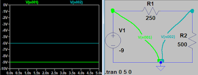
My first thought on creating the correct RS423 voltage for the keyboard was to drive down +12V to +6V and to drive up -9V to -6V with voltage dividers. To divide voltage in half, you simply need two resistors of the same value in series, with one end of the series hooked up to +12V and the other to GND, and then tap your +6V from where the two resistors are connected to each other. To cut voltage by 1/3, resistor 1 (from -9V) must have half the resistance of resistor 2 (to ground).

LTSPICE circuit simulation showing the original input voltage divided by 2/3.
My original idea was to use an Arduino to drive the scan codes, and source the power from the Arduino from the divided -6V output. I would wire -6V to the Arduino's ground, and the computer's ground to the Arduino's VIN. From there, I could use an NPN transistor with its emitter hooked up to the same -6V to expose the the scan code pin to either -6V or the divided +6V depending on its activation. The circuit worked fine in theory, but I ran into some practical hurdles. The original resistors I picked for the voltage divider allowed for just a small amount of current at those voltages, and with the demands of the Arduino, soon my voltage dividers were reading nowhere near their intended values. I ended up with just over a volt showing up across the +5V and GND pins on the Arduino, not even enough to power it on.
My next thought was to lower the resistance values on the voltage dividers. I thought about Ohm's Law and how much power would be required for higher current, and grabbed from my 1/2-watt resistors and put the 1/4-watt resistors away. This time, I went with an order of magnitude less resistance, but the Arduino still only showed a little bit over 2 volts. Using the unregulated power pins didn't seem to help the situation either. You might be wondering "Why not just go with really low-value, high-wattage resistors?" Well, the electronics store was closed, plus there's no reason I should ever use anything more than a 1/2-watt resistor unless someone is paying me to do something specific.
Finally, I decided to hook up the Arduino not to the divided -6V and GND from the computer, but to the divided +6V and the divided -6V, so that hopefully the regulator would have a better shot at regulating down to +5V. However, this still caused the Arduino to read just 3.7V or so across the 5V pin, and it smashed my high-side divider (which was supposed to cut +12 to +6) down to just 0.8V. Clearly, even if I could get the Arduino working, it wouldn't generate the needed voltage for the scan code! And besides all this, the NPN transistor was somehow transferring its +0.7V base bias to somewhere else in the circuit, as I could see values differ by 0.7V when it was installed versus not.
(Mind you, I'm testing all this using a proper bench power supply, not from the computer itself at this point, so there is no risk of damaging the Soviet goods.)
Approach #2 - Two 7805 Voltage Regulators plus NPN BJT or N-channel MOSFET
The 7805 voltage regulator is a TO-220 packaged device that simply takes an input voltage, and a ground voltage, and can supply some amperage at +5V from ground. No more messing around with specific currents coming from a voltage divider; I wanted the voltage regulator to handle everything for me. The idea here was to use one to regulate +12 down to +5, and to regulate -9 (as if it's the ground input into the 7805) up to -4V. I was still trying to drive the logic from the low side (-4V) to use an NPN transistor (or even a MOSFET to properly switch on voltage at the gate rather than current at the base). (Also note that my bench can't supply -9V; it only supplies -12V, so really my regulated line is sitting at -7V for testing.)
Polluting the Groundwater
With all this wired up, the voltage regulators would show a spread of about 12V between their output pins. However, by inserting the Arduino on the regulated low side between -7V and GND once again, the circuit wasn't able to provide enough juice to it. I had the Arduino regulate itself from both the regulated lines at +5/-7, and once I wired it up, what would normally show a 12V spread was now showing something more like a 9V spread. At least I managed to get the circuit to power up. However, the voltage of the switching side of my NPN transistor (and even a 2N7000 N-channel MOSFET) relative to computer ground would only swing between +5 and roughly -0.5, still not enough to show the computer a proper Low signal for the keyboard scan codes.
Something must be polluting the groundwater, as the voltage between the low-side voltage regulator and the computer ground seems to vary slightly, and is much higher than it should be. I can imagine, since the 7805 consists of various transistors and diodes, that it must not like providing an output voltage to something that is actually using it as a ground rather than as the high-voltage source. I might have to go back to a voltage divider once again...
Approach #3 - One 7805, One PNP, and Something for the Negative Side
I thought to myself that it must be necessary to regulate the logic from the high side rather than the low side, since the 7805 probably doesn't like when its output is used as a ground rather than as the high-side input. I decided to use the 7805 on the +12V side to both regulate the High RS423 signal and provide +5V to the Arduino. This means that when the Arduino outputs +5V on its serial line, then the serial line can be driven up to the same value. However, when it outputs 0V, then the serial line will need to be driven down to -5V, which could be provided by the low-side 7805 or by a plain voltage divider once again. I needed to find a way to make the Arduino pin behave as if it would output either +5V or high Z, since with high Z, I could use a pull-down resistor to bring it to -5V.
As it turns out, for a PNP transistor, the emitter must be at a higher voltage than the collector, thus the emitter is hooked up to the voltage source rather than to ground as it is when an NPN transistor. Thus, the base is always negative with respect to the emitter, and once you drop the base at least 0.7V from the emitter, current will start flowing through the base and the output of interest will rise to the 5V provided from the regulator. However, when the Arduino pushes 5V to the PNP's base, then no current will flow through the transistor since the base voltage will be the same as the emitter voltage, thus the voltage at the output of interest will drop to the output from our negative-side voltage regulator or divider that is supposed to be providing -5V.

Here, it is shown that as the base (in blue) swings from 5V to 0V, the output of interest at the PNP's collector (in green) will swing from -5V to 5V. The red line indicates the current through the base.
And if I need the RS423 signal polarity reversed, I can invert the Arduino's serial line with another transistor or an inverter IC. Luckily, the signal did not need to be inverted; the output of the PNP transistor is normally low and pulses high, which is the same type of signal produced by the MS7004 keyboard.
In practice, the -9V line was showing -8V with the LM7805 voltage regulator sitting on it, and its regulation treating 0V as high and -8V as ground means the regulated voltage was only sitting at -3V relative to ground. This would not be enough to drive the RS423 signal. Rather than grabbing a variable voltage regulator, I decided to simply build a plain voltage divider and connect its output to the collector of the PNP transistor. At first, I decided to use a 4700-ohm resistor and a 6800-ohm resistor for the voltage divider, but the high-side input seemed to be getting squished. I found that a 330 and 470-ohm resistor did the trick, but then realized I read the measurements originally from the wrong spot. With the original resistors and the oscilloscope probing from the correct location, I found out that both these resistor configurations are suitable for the job. (As for which one keeps -9V more true to -9V... I'm not sure, but I'd wager the higher-value resistors would do the job better.)
Before wiring up my Arduino, I needed it to send the correct values to the system in order for any key presses to be registered. There are two things to consider here: first, the keyboard introduces itself to the computer (and indicates the absence of errors) by sending the bytes 0x01 0x00 0x00 0x00 at once following power-up. Secondly, the ODT (Octal Debugging Terminal) of the PDP-11 only accepts a few keys from the keyboard, such as the numbers 0-7, the letter B (followed by 3 letters indicating a device driver location to load), and the letter R (indicating a CPU register number). To avoid pulling my hair out debugging something that's not a problem, I referred to a graphic of scan codes for the LK201 PDP-11 keyboard interface and programmed the Arduino to spit out the number 4 (0xD0) once every second following the 4-byte handshake explained earlier, which itself is sent one second following power-up.

It still took me a few power cycles of the computer before I finally saw the desired output, especially making sure that RS423-compatible voltages would be output by the circuit, but eventually I saw a line of "4"s growing across the screen every second, corresponding to the serial pulse waveform being monitored by the oscilloscope.


Ironing Out Last-Minute Details
In practice, the -9V line was showing -8V with the LM7805 voltage regulator sitting on it, and its regulation treating 0V as high and -8V as ground means the regulated voltage was only sitting at -3V relative to ground. This would not be enough to drive the RS423 signal. Rather than grabbing a variable voltage regulator, I decided to simply build a plain voltage divider and connect its output to the collector of the PNP transistor. At first, I decided to use a 4700-ohm resistor and a 6800-ohm resistor for the voltage divider, but the high-side input seemed to be getting squished. I found that a 330 and 470-ohm resistor did the trick, but then realized I read the measurements originally from the wrong spot. With the original resistors and the oscilloscope probing from the correct location, I found out that both these resistor configurations are suitable for the job. (As for which one keeps -9V more true to -9V... I'm not sure, but I'd wager the higher-value resistors would do the job better.)
Before wiring up my Arduino, I needed it to send the correct values to the system in order for any key presses to be registered. There are two things to consider here: first, the keyboard introduces itself to the computer (and indicates the absence of errors) by sending the bytes 0x01 0x00 0x00 0x00 at once following power-up. Secondly, the ODT (Octal Debugging Terminal) of the PDP-11 only accepts a few keys from the keyboard, such as the numbers 0-7, the letter B (followed by 3 letters indicating a device driver location to load), and the letter R (indicating a CPU register number). To avoid pulling my hair out debugging something that's not a problem, I referred to a graphic of scan codes for the LK201 PDP-11 keyboard interface and programmed the Arduino to spit out the number 4 (0xD0) once every second following the 4-byte handshake explained earlier, which itself is sent one second following power-up.

The schematic of my final keyboard emulator design. Note the red stylized "LT" letters are a trademark of Linear Technology, just in case you are not familiar. The LM7805 is a common part.
It still took me a few power cycles of the computer before I finally saw the desired output, especially making sure that RS423-compatible voltages would be output by the circuit, but eventually I saw a line of "4"s growing across the screen every second, corresponding to the serial pulse waveform being monitored by the oscilloscope.

The March of the Fours begins...

The Arduino and circuit involved to make keyboard emulation happen

The waveform of the number 4 as an LK201 scan code. I just noticed that the low side only goes down to about -2V according to the oscilloscope, rather than the -4 to -6V expected. Oh well, it worked regardless.


Comments
Post a Comment