The story of those awesome "shaky benches" from TechWeek Dallas 2016
For all this time, I have touted myself as someone familiar and adept at working with hardware, and try to stay on top of all the latest & greatest gadgets in the arena. Of course, that's very hard to do, and eventually you will find that you've ignored something that virtually everybody else in your circles seems to have already played with. For me, that was the WS2812 LED strip. Sure, I've used WS2812 lights recently in an IoT sensor product, but really Stacy wrote that code and we are only driving one of them per board, so it's not truly all that interesting. Now, it's time for me to get serious with what the WS2812 lights are really meant for.
What is (was) TechWeek?
TechWeek is an event held in cities across the country. It attempts to discuss various tech trends by bringing together numerous panel discussions on things such as ed-tech [1] [2], healthcare, and smart cities, plus individual speakers talking about things like the path to driving a startup culture inside a large enterprise organization (in fact a "big bank", if "large enterprise organization" wasn't already scary enough for you). The event began in earnest on 11/2, preceded by a Halloween party on Monday 10/31 and tours around various innovative corporate campuses on 11/1 (including at the aforementioned big bank, which I helped facilitate), and wrapped up by an epic concert featuring The Neighbourhood and others on Friday 11/4. The keynote was given on Friday by Alexis Ohanian, co-founder of Reddit. There are other things to do besides plenty of networking opportunities, such as startup pitch contests, startup job fairs, and lots of drinking & partying & concerts besides just the one on 11/4.
The highlight of TechWeek for me was the "Surround Sound" event at The Bomb Factory in Deep Ellum, which is where most of TechWeek took place. At this event, attendees would be exposed to various ways in which sound could be transduced and manifested into other sensory experiences such as visual or haptic effects. Among the pieces presented were an artist on-stage making a 3D interpretive painting with an HTC Vive, a large LED wall producing art based on live spectral analysis of the music coming from the DJ booth and an additional microphone, holographic screens where you could dance with people across the room... and my piece.
Getting in on this not just by who I work for
One of my friends from the Dallas Makerspace approached me sometime over the summer (maybe end of July or August) about working on a project that would fit the essence of what Surround Sound would be all about. I told him to keep me posted, and it wasn't until mid-September (at the DMS Open House) when he mentioned with certainty that he'd be participating and building out his dream for the event. It really had to do with getting paid the grant money; it would have been an expensive project to take on and have the potential of something failing or not working out. Unfortunately that left only about six weeks to the show, thus I was recruited to assist given my knowledge of LEDs and electronics.
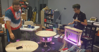
Nick owns a print shop and design studio, and is a very crafty fellow in the realm of everything from graphic design to embroidery as well as other unrelated hobbies such as shooting and ammunition reloading. As such, he put himself in charge of fabricating the actual components of the piece. This included two circular benches 4 feet in diameter with little tiny holes cut out in the top of the plywood for light to shine through. The benches were covered by custom-cut white Spandex, which the lights from the holes projected nicely onto. Speaking of the lights, there would be 240 WS2812 LEDs in each bench, broken up into strips of 10, 20, and 30, located in each quadrant of the circle. At the base of each table would be a ButtKicker™ amp that could deliver 1500 watts at 2 ohms worth of frequencies between 1 and 200 Hz. This amp was not really designed for propagating audio through the air, but through some solid medium like a chair that you sit on and really feel the bass tones. Then, there would be a control table, also fashioned out of plywood and covered with Spandex, that would have 160 WS2812 LEDs in it in addition to two sonar sensors mounted into 3D-printed coverings over holes cut into the plywood. All of the plywood was cut on the CNC router at the Dallas Makerspace and was designed to be press-fit -- no nails or staples were used to hold the furniture together.

Then there was Darcy, tasked with creating the audio effects to be used in this installation. The idea was to allow party-goers to manipulate the audio signal into the benches somehow by using the sonar sensors. She worked out calibrating the sonar sensors to respond to objects moving at various distances. The sensor outputs were consumed by me through the PWM pins of the Teensy she was using (v3.2) to read the sensors, and also interpreted for the sake of performing sound synthesis with the Teensy Audio Adaptor Board.
My colleagues downstairs worked with a publicity company who managed the engagement with Nick and Darcy. They were impressed at the scale of my network when I mentioned I knew them and they had spoken of this project with me, and then they thought it was really cool when I told them I would be helping out on the project too!
My colleagues downstairs worked with a publicity company who managed the engagement with Nick and Darcy. They were impressed at the scale of my network when I mentioned I knew them and they had spoken of this project with me, and then they thought it was really cool when I told them I would be helping out on the project too!
Affecting Effects
I was brought in to do the lighting effects, despite that I practically minored in sound synthesis in college. It turns out I have a lot more LED experience of recent note, so that makes sense. In fact, I briefly dappled in using mathematics to make art (or at least wonky patterns on 3D graphs) in college, so I applied the similar mindset (if not my long-lost knowledge of multi-variable calculus) into making the LED effects for this project. Since this was not a true LED matrix, but rather 3 bands of lights around the circumference of the benches, it didn't make sense to do something over-complicated and two-dimensional. A simple yet compelling one-dimensional effect that can go in a circle is simply an undulating sine wave. Here is my first crack at such a wave:
This wave was built by calculating the value of sin²(x) at various points along 0 <= x < 2π. Originally I used a step size of 2π/61 because my prototype had 61 LEDs, but later I changed the step size to be 2π/100 to be standard. Now, sin(x) produces a very wide waveform relative to a single period, and doesn't make a lot of distinction between lights that should be on versus lights that should be totally dark. By squaring the sine of x, values close to 1 become even closer to 1, and values close to 0 become even closer to 0, thus making the waveform even "peakier." Actually, I avoided doing an annoying squaring operation by looking this function up in Wolfram Alpha and finding out I could calculate (1 - cos(2x))/2 instead. And speaking of looking things up, I stuffed all the output values from this function into a lookup table for convenience later. As the program would constantly be calculating the same values over and over (and wasting an untold amount of CPU cycles in doing so), I figured the lookup table would be best for performance in the long run. (All the people who developed wavetable audio synthesis products would probably agree with me.)
I also coded additional lookup tables to vary the color of the LEDs over time. Originally we would swing them from red to purple to blue based on the value of one of the sensors. The sensor would influence which index of the color lookup tables we would access; the same index for both the red and blue channels would be used. (For this case, green could always stay 0.) These lookup tables were based on simple ramp functions that slowly eased the value of that color channel from 0 to 255, and then held it constant; one channel's graph looks like the other one reflected over the Y axis. Then, the speed of the undulation (the wave spinning around the circle) was affected by interpolating the other sensor's value to a number between 1 and 14, which corresponded to the offset we would add to the lookup table to calculate each LED's intensity. This way, the waves would appear to move around the benches and table.
Stressing Over the Finishing Touches -- Heck, Just Getting It To Work!
After a couple more weeks where Nick & Darcy were working on their parts, I got engaged again to make further modifications to the LED effects and to help with the assembly. One enhancement was to change the colors to sweep from red to white to blue. To change purple to white, I took advantage of the green color channel. The function for green is simply the negative absolute value of x so the lookup table ramps from 0 to 255 and then back down to 0. Now each RGB channel has its own lookup table. We also continued to toy with the exact formula producing the sine wave, and I made some changes to the sine wave lookup table so that the same lookup table could be used among the three different-length LED strands below the bench.
The few days prior to the event were quite stressful, and we put in long hours to get the finished product working. The hardware we were using wasn’t even nailed down, so I attempted to use a Raspberry Pi to drive the LEDs and perform audio signal analysis all from a single source. It ended up being overly complicated; audio signal analysis doesn’t go incredibly fast on the Pi, and lots of things would need to be downloaded and compiled for it to work. It turns out that doing such analysis probably wasn’t even necessary anyway because people really seemed to enjoy adding simply the bass drops; it is something concrete and distinct that folks can understand rather than having one of us standing around the whole time explaining to people how to compare some subtle property of the audio with the audio signal in general. Lastly, I tried to implement some beat detection with the Arduino so as to synchronize the bass drops with the beat of the music and perhaps do one or more bass drops per beat. Ultimately, time ran out for that enhancement. The hardware we ended up using consisted of a Teensy in the control table for sensors and sounds, an Arduino Uno in the control table to drive the lights, and then the benches had either an Arduino Uno or Leonardo in them to run their lights, depending on whatever we had on hand.
Since the Teensy reading the sensors needed to drive signals consumed by the other Arduinos to produce the light effects, I had to be careful not to use outputs on the Teensy that overlapped with the pins that the audio board needed. For this reason, I used three specific PWM pins to output to the three other Arduinos so that each pin would only have to drive one TTL load. However, the Arduinos would need to read these signals in as analog, so I used specific values of resistors and capacitors to make an RC circuit with characteristics that made me happy. The biggest thing to consider in an RC circuit is the tradeoff between signal rise time and ripple. Too much ripple in the output would cause bizarre pulsing of the colors or a confusing change in the rate the sine wave would spin around the table. However, too much rise time would cause the sensors not to react fast enough to make the effect make sense to people interacting with it. I played around with some websites to calculate the theoretical values of resistors and capacitors I needed, ultimately settling on 100 ohms and 10 μF (if I recall correctly), and then verified their behavior with an oscilloscope. Once I was satisfied, I added the components to the breadboard and wired up the RC circuit to the analog inputs on each device, and then the appropriate outputs on each device to the LEDs.
Wow, what a mess…
Apparently WS2812 LED strips are quite sensitive to noise. This pernicious problem can come from all sorts of sources, including shoddy soldering/cabling or EMI through unshielded cables. Thus, for our long cable runs, we spliced up twisted-pair CAT 5 cables to provide power, ground, and data to each device. We twisted up regular wires using a power screwdriver/drill to provide the same type of cross-talk cancellation between our LED light strips. The problem is there were so many LED strips under each table that it required soldering almost 40 wires per table. There's not a lot of landing room on the pads once you've cut them up, and remember we're soldering in some cases upside-down right on a plywood surface! Talk about a fire hazard. And even with all this precaution taken, we still had a big issue with noise, but only on the art project. The lights would work just fine on a regular uncut LED strip, but the exact same code would produce all kinds of odd rainbowing and strobing effects in the installation pieces. We tried reducing the noise by putting a resistor on the data line, but that didn’t help. We then brought in Stacy, resident capacitor expert, to solve the problem that way. Since the power line was noisy, she simply placed a capacitor across power and ground on one LED strip in each art piece, and now all that weird flickering and strobing went away, leaving us with the desired effect. Of course, all this messing around with wiring didn’t come without occasionally shorting our power supply or zapping ourselves with 5V at 60A. I can’t claim to have felt anything, but Nick says he got zapped a few times. Maybe I’m just immune to 5V shocks anymore, even at 60A!
The audio synthesis code was a bit suspect at times too due to various bugs writing the frequency and amplitude to the two different audio streams. I found out that each sensor was writing to one single stream in turn, very rapidly, which was probably not the desired effect. We played around with “glitches” by writing various sensor parameters as either amplitude or frequency to the audio stream until we found something we liked. This made me think: when will they come out with SuperCollider for embedded systems?
Wastes of Time, Including That Mother-F***ing Map Function
One thing that really wasted my time was trying to use the map() function provided by Arduino. Literally all this function does is solve y = mx + b by taking two points of x and two points of y. That’s really how they should describe it in the documentation. Instead, they go on about some hand-wavy type of description that doesn’t make it clear what kind of boundary conditions exist when you use this function. Apparently, there are no boundary conditions, and I needed them. The PWM pins from the Teensy were basically sending me values between [0, 32) but scaled to between [0, 1024) because that’s the range of the ADC on an Arduino. As I received input, I needed it to consider what would be actually appropriate ranges for those input values because they were being directly used as the indices for our lookup tables. By simply re-implementing the map function to do what I needed it to do in the first place, I could have saved having to debug program crashes from index-out-of-bounds errors, which resulted in hours of busting my head on why the LED effects would freeze. Of course, I could have just added min()’s and max()’s to the output from map(), but by that time, I was ready to call up the university of whoever made that function (or at least the documentation for it) and tell them to revoke his or her degree.
Another thing that sank a lot of my time was chasing down the correct signal lines. As we added all the devices to the breadboard in the control table, the circuitry became rather jammed and hard to work with. Often, I would find myself probing the wrong output when trying to test why the analog signals were causing different or undesired results between the different pieces. On the final night before the big show, I wasted about 80 minutes in this manner trying to debug one single problem. By the time you’ve worked so much on something and are feeling a lot of pressure, it can be easy to overlook such simple things as you stress the technical issues that you think it could be.
But When It’s All Said And Done…
Nevertheless, despite what it could have been and what it ended up being, we all believed it worked out the best for what the show was. Anything more and it could have been overwhelming or confusing (or even annoying) to people, despite how much fun it would have been to get geeky with signal processing to, say, add in sparkling effects, add more spinning waves, or even use a solenoid to bang a drum. Here is a short video of what we produced:
The code for the project is on GitHub at https://github.com/Drc3p0/SurroundSound . Some highlights from that code:
We ended up going with sin^6(x) as the function to produce the wave in our lookup table. It was achieved with this for loop:
for (i = 0, x = 0.0; i < 100; i++, x += (PI / double(100))) {
//sin^6(x):
overallAmplitude[i] = ((-15 * cos(2.0 * x)) + (6.0 * cos(4.0 * x)) - cos(6.0 * x) + 10) / 32.0;
}
The lookup table consists of 100 float values. Originally the literal 100 was a constant called QUANTA. So, no, the actual code does not have me writing double(100) like some kind of weirdo.
The benches had 240 LED lights apiece within three circles. One circle had 40 lights, the second had 80, and the biggest had 120. However, these three circles were treated as a single string, so the first 40 were drawn on the string, then the next 80, then the last 120. But it’s in fact even more complicated than that: when the tables were wired up, each quadrant (i.e. section of 10, 20, and 30) were wired together before the string would go on to the next quadrant. This is why the tableSide variable exists in the showFrame() function. The variable p inside each for loop keeps track of specifically which pixels from each circle are being drawn, and the variable scaledIndex converts the proportion of (pixel index : string length) to find the pixel index relative to the lookup table of length 100.
for (int p = int(PIXELS_INNER * beginRatio); p < int(PIXELS_INNER * endRatio); p++, pp++) {
scaledIndex = p * 100.0 / PIXELS_INNER;
rVal[pp] = figureColor(scaledIndex, redColor[colorIndex]);
//etc...
The lookup tables for red, green, and blue values were defined as bytes rather than floats in order to save memory. Had I chosen floats, the Arduino Uno would not have enough memory to store all the lookup tables I desired. Originally I wrote the functions providing the lookup tables to provide floating-point outputs between [0, 1]. When using a byte array, I rewrote them to output integers between [0, 100]. This allowed me to scale the final output by 2.55 rather than 255 when coming up with the final intensity values for each pixel.
Before new data would be pushed to the LED string, the color value for each LED would be stored into an array of type byte as well. The value in the array was derived from solving an equation relating the LED’s position index in the strip and the motion offset of the sine wave to which value of the lookup table it should get for its intensity. This intensity value was used to scale the color values from each channel’s lookup table, and the index used to look up the channel values was given by the most recent reading from one of the sensors. The final color of each LED is given by this function:
byte figureColor(float scaledIndex, float colorAmount) {
return overallAmplitude[int((waves * scaledIndex) + stringOffset) % QUANTA]
* colorAmount
* 2.55;
}


Comments
Post a Comment